|
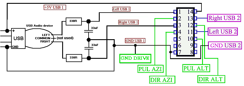
Suggest of filter circuit to couple USB audio device with "pulse/direction" driver |
|
||||
| Esta página em português |
|
|||
Choosing a filter:
1- If your USB audio device is a "true SJ588" (see here how to buy and recognize your audio device), then use the COMPLETE filter circuit shown. These audio device is a PWM device (not analog audio), then the output must be filtered before input on your driver. Ignore questions 2 to 5 below.
2- OK, your audio device is "HY554", "Fake SJ588" or some "B-class-output" device. Remember to bypass output capacitors (if exists).
3- Before any test, first properly configure your computer's audio, as described at "Audio devices configuration" section of main page. Then start SoundStepper, choose "Change Configurations" in initial window, choose the correct device at "Audio devices and motors" and enter the TEST window:

4- Using Soundstepper "DC test" in analog mode and at maximum volume, measure output voltage swing from (-) to (+) for left and right channels. Use USB connector ground for reference. Read your stepper driver's manual, look for the levels of "Pulse/Direction" inputs, see if is compatible with output voltage levels from audio device.
5- If the voltages are compatible, first try couple directly Left audio channel to PULSE input, and Right audio channel to DIRECTION input, GND to GND. Maybe the outputs are noisy, then the driver will interpret noise as extra pulses. If it's occurring, then use a low-pass filter, as shown. Do the same for all your USB audio devices (if more than one).
Simple Low-Pass filter for SoundStepper with Pulse/Direction driver:

6- If the voltages are incompatible, or the outputs are extremly noisy, You muse use the COMPLETE filter, with a Schmitt trigger as "74HC14" or equivalent, to compatibilize the levels. If You have 3 motors (and 3 USB audio devices), You can use pins 6,7,8,9 of 74HC14 for "USB3".
Complete filter with Schmitt Trigger for SoundStepper with Pulse/Direction driver:

OBS:
74HC14 pin description: data input=1,3,5,9,11,13 output=2,4,6,8,10,12 GND=7 Vcc=14