
|
USB Audio devices for SoundStepper |
|
||||
| Esta página em português |
|
|||
1- What kind of drive do You want? a home-made analog, or pulse/direction?
For SoundStepper suggested analog drive (current controller), the BEST (by far) is the "True SJ588" but is possible to use any device;
For pulse/direction drive (commercial or home-built) is better to use an pure analog audio device ("HY554", "Fake SJ588" or some "B-class-output", many based on CM-108 or CM-109 chipsets), but is possible to use any device;
See more about amplifier classes and PWM here:
http://en.wikipedia.org/wiki/Amplifier
http://www.bcae1.com/ampclass.htm
http://en.wikipedia.org/wiki/Pulse-width_modulation
2- How to recognize the correct device before buy?
Ask the seller for the Windows device name, and for photos of device board, outside of plastic cover.
If the windows device name is only an uppercase "USB AUDIO", this is a "True SJ588" (based on chip TP6911 from Tenx, a "D-Class-output" PWM device), good for analog drives;
Any devices with another names (like "Generic USB audio device" for example) will be "HY554", "Fake SJ588" or some "B-class-output", many based on CM-108 or CM-109 chipsets, good for pulse/direction drives;
By photos, is difficult to recognize the "True SJ588" from fake ones, but we have some hints, mainly the output capacitors, the TP-6911 chipset, the "SJ588" name on board, the many small components on the back side, and the un-grounded common output.
Three different models of "True SJ588" (click on photos to open large in new window):

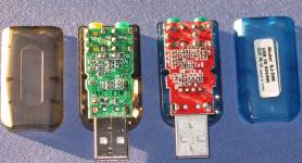
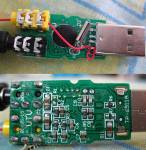
And this is a True SJ588 sold as HY554:
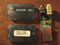
IMPORTANT: Do not rely on photos or names, always ask to seller for internal photos and the windows device name!
Fakes SJ588 (click on photos to open large in new window):


The external case of an "Fake SJ588" is identical to original, but internally we can see some differences:
- Many small resistors and capacitors in front, none in the back;
- One single LED in the middle (the true has 2 leds, one left one right).But this may vary.
- In the back, we can see the "common" terminal wired to ground (the true sj588 does not connect common output terminal to ground!)
- Without output capacitors ==> it produces DC from Left/Right to common outputs. Left/Right are always at 2.3V and common=GND=0V;
- These fake device uses a CM-109 chipset, is a "B-Class" audio device, like "HY554" in SoundStepper main page.
HY554-like devices (You can see the OUTPUT CAPACITORS):
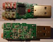
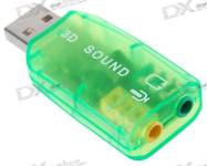
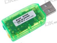

- On second and fourth images they are obvious, on the first image they are the large "cubes" between the output jacks "100 6V".
- The first one have a large number of backside components, like True SJ588!
And this is a CM-109-based device, but the common output is at reference voltage, is a True SJ588 equivalent for analog drives!!
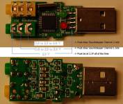
- Yes, the major difference between True and Fake SJ588 for analog drives is the reference voltage! The true do have a reference on common output, the fake haven't. And the analog drive is much better when having a reference voltage.
- It fits perfectly to analog amplifier like SJ588, is even better because not need twice low-pass filter (input stage).
- The only change is replace the four 47K resistors (from this page) to 33K ones, because the voltage swing (3V) is smaller than True-SJ588 (5V).
- It was bought here, but I recommend doesn't look for these specific device, this is a "lucky buy" of a Fake-SJ588.
3- With device on hands, how to ensure which device type it is?
Plug the device on computer. If the windows device name is only an uppercase "USB AUDIO", this is a "True SJ588" (based on chip TP6911 from Tenx, a "D-Class-output" PWM device), good for analog drives;
Any devices with another names (like "Generic USB audio device" for example) will be "HY554", "Fake SJ588" or some "B-class-output", many based on CM-108 or CM-109 chipsets, good for pulse/direction drives;
Before any test, first properly configure your computer's audio, as described at "Audio devices configuration" section of main page;
Start SoundStepper, choose "Change Configurations" in initial window, choose the correct device at "Audio devices and motors" and enter the TEST window:

Set the volume at 100%, analog drive method. Use "Audio Test", and test both channels once at a time, and check with a headphone if it works!
Use "Direct Current Test", and With a multimeter, measure the Left, Right and Common output voltages when changinging channels 1 and 2 (once at a time) from (0) to (-) and to (+). Always use the USB ground for reference. Take note of values;
If the LEFT and RIGHT channels are always at 0V, the device have output capacitors. Bypass it!
If the COMMON output is 0V, this is a HY554-like device. Use with pulse/direction drive or build a analog drive for HY554. Alternative: At your own risk, Instead of using potentiometers to find the "center" voltage, you can find in the reference voltage at pin 31 (LOBS output) of CM108 and apply it to pins 10 and 12 of CA324, without potentiometers. But I did not tested it, You must experiment.
With both channels at (0), check if Left, Right and Common are all at the same voltage (not zero volt!). Check if the COMMON output does not vary the voltage when sliding controls from (-) to (+). If yes and yes, it's a TRUE-SJ588 or equivalent, good for analog drives;
Calculate the LEFT and RIGHT channels voltage swing, when sliding controls from (-) to (+). If the voltage swing is > 4.5V, it's a TRUE-SJ588, build the analog drive as described. If the voltage swing is less than 4V, replace the four 47K resistors (from this page) to 33K ones.