Analog controller for SoundStepper with "True SJ588" (based on chip TP6911 from Tenx, a "D-Class-output" PWM device)

Analog controller for SoundStepper with "True SJ588" (based on chip TP6911 from Tenx, a "D-Class-output" PWM device)
Drawing for SoundStepper circuit in "island" 1x1 protoboard, like this:

Only for "SJ-588" or other "D-class" amplifiers, without output capacitors and with minimum 4V output voltage swing.
OBS:
Sets of resistors to be (proportionally) matched are colored in diagram
Resistor values differs from other diagrams because they was optimized for "SJ-588" device specific output values
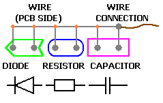
Used Symbols:

Diagram:
List of components for "SoundStepper controller for SJ-588" circuit.
Resistors:
(2) RL (to be calculated for 1V voltage drop at motor nominal current)
(8) 330R x 1/8W
(4) 470R x 1/8W
(2) 1K x 1/8W
(4) 22K x 1/8W
(4) 47K x 1/8W
(4) 82K x 1/8W
Capacitors:
(13) 100nF x 25V ceramic
(1) 500uF x 25V eletrolytic
CIs:
(1) TDA8566 "Q"
(1) LM324 or CA324
Diodes:
(8) 1N5818 or equivalent (Schottky 30V isolation, 1A nominal 20A max).
Standard rectifiers like 1N4001 may be used too, but don't offer the
same protection as Schottky diodes.
(2) LEDs (diag and clip)
Other:
Protoboard "island" 1x1, 1/10 inches (2.54mm) hole-to-hole, 15X22 holes or greater
Wires
Stepper
Heatsink
SJ588
Power Source (12 to 16V)
PC with Windows and Soundstepper
USB cable
Power and motor connectors
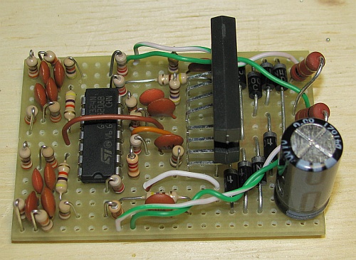
Component side:

Protoboard soldering side:

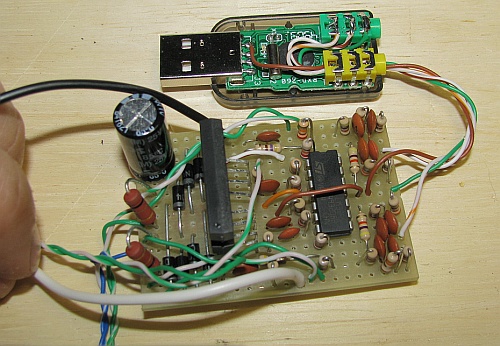
Done, with SJ-588 connected:
