
|
SoundStepper - Realtime telescope controller for Windows |
|
||||
| Esta página em portuguęs |
|
|||
General concepts: |
User guide: 4-Software installation and first use |
Overview
SoundStepper is a 100% software telescope controller, for Windows.
Using audio hardware to real-time control step motors, it requires only simple external analog current amplifier to operate.
Most systems of this type is written in any language for MS-DOS, because Windows is very poor for real-time control. This means using the CPU in dedicated mode, and lose all possibilities of using the computer for other purpose simultaneously with the telescope control, such as for example a sky map, autoguiding, or capture images from a webcam or CCD.
In this system, for Windows, the CPU consumption is minimal, and can be used almost all the processing for other activities, without prejudice to control. The trick is to use the computer's sound hardware, which has data buffers and processing itself, to control step motors in "real time". What SoundStepper does is to generate a data stream and send it to the sound system, which in turn is responsible to play like a song, in constant speed, no flaws, leaps, without the need for real-time CPU.
Open source and public domain project.
Initially designed, developed and used by brazilian programmer and amateur astronomer Maciel B. Sparrenberger
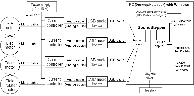
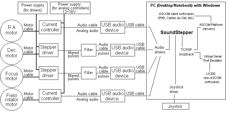
Complete system block diagram:
a) Using analog current controllers:
b) Using commercial "pulse/direction" drivers (suggest of filter here):

c) Arbitrary mix of analog current controllers and "pulse/direction" drivers:
FEATURES
Frequently asked questions
Do I need to compile SoundStepper?
A: No, the executable file is included in all distribution packages
Can SoundStepper control altazimutal mounts?
A: Yes, beginning with 5.0 beta version.
There is an alignment procedure and misalignment error correction for althazimutal mounts?
A: No, the mount must have perfectly orthogonal axes and must be precisely leveled. These error correction routines are in the "roadmap", but for future versions.
Does SoundStepper have any other application besides telescope control?
A: Yes, if the source code is modified, SoundStepper can work as a microstepping driver, but with simplified analog electronics.
What kind of audio devices can be used?
A: Any device that can handle output DC signals, that is, without using output capacitors.
What type of step motors can be used?
A: Bipolar steppers, or unipolar steppers wired as bipolar. The voltage depends solely on the amplifier. Since the suggested circuit works on 12V, it is recommended that the rated voltage of the motor is less than 8V. Using commercial "pulse/direction" drivers, any kind of motor compatible with driver may be used, including 3 or 5-phase step motors.
I have another question, where to get help?
A: See "Contact" section below.
Source and development
The code was developed and compiled in Delphi (Delphi7 Second Edition, 7.2), with INDY Sockets version 9(VCL) package installed (http://www.indyproject.org).
The complete source code is available at Sourceforge (Project page -> Develop -> SVN Browse code).
The project configuration files were included with the source, so just open the SoundStepper.dpr file in Delphi, and you can compile as was done for the release files.
Delphi was chosen because it offers great performance and simple alternatives for:
No need to interface with serial ports, parallel or USB. The interfaces are listed above: audio, keyboard, mouse, TCP/IP, and files (text and binary).
The SoundStepper is based on thread and message loops. It was done so that the user actions does not lock vital functions, which must not stop, and does not interfere in one another.
Although has been reported SoundStepper works on Linux (using wine), in my view the biggest challenge of portability are the Windows messages, not supported under another operating system.
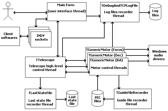
SoundStepper threads block diagram:
History
V.0 (Oct/2006):
The "embryo" of this system was written in c for MS-DOS, and had needed a dedicated computer, controlling the RA motor through parallel port, with microstepping.
The V.0 controller had rudimentary PEC/NPEC system already, with manual controls only, saving the training result in a file, as well as the end-of-rail position and the automatic return to the starting position.
V.1.0 (Mar/2007):
Implemented the RA motor control system through audio output (for Windows) written in Delphi, but with the same manual rudimentary controls, and PEC/NPEC, which required the reference points markup.
Some (very slow) centering controls were added, as well as pause, and help buttons.
There was no guiding, the screen was polluted and unintuitive, and sometimes the sound had gaps, creating jolts.
V.1.1 (Jun/2007 - not distributed):
Added a rudimentary guiding system, only in RA axis, using the parallel port, and the configuration file (SoundStepper.ini)
V.1.2 (May/2009 - not distributed):
Added declination guiding, also in rudimentary form, using parallel port to get signals from PHD Guiding.
The code was becoming a mess, because it was not object-oriented: Or the whole system would be redone, or could no longer be mantained.
V.2.0 (Jun/2009 - not distributed):
New and easy user interface, already similar to 3.0, with much more intuitive controls.
Implemented manual guiding controls, more extensive configuration file, and modified the recording of guiding points, from float to int.
The code was rebuilt, trying to follow object-oriented concepts.
Improved RA axis start/stop procedures.
However the system was still doing audio gaps when maximizing or minimizing windows, and had no "centering rate" controls.
V.3.0 (Jul/2009 - not distributed):
Multi-threaded version, with a dedicated controller thread and another for the user interface.
No longer audio gaps. Identical to version 2.0 user interface.
V.3.1 (Aug/2009):
Center and find controls added ("Control Box"), using keyboard arrows.
Smooth motors acceleration and improved intuitiveness of the controls.
Return interrupts are now permitted. Redone the project documentation.
V.4.0 (Sep/2010):
Modified the algorythms to use USB Audio devices, supporting DC operation, ensuring better control of motors and releasing the default computer audio output to normal use.
Add control for up to 3 motors (RA, Dec and focuser).
Added ability to control any type of equatorial mount, and the "sync", "go-to" and "flip" controls.
Configuration screen, contain audio operatioin parameters, mount type and limits.
Monitoring and compensating the audio sampling frequency variations, the systems become immune to this changes.
The waveform became configurable to improve motor movement linearity, lowering wooble in low-reduction mounts.
The screen texts was moved to .ini files, allowing easy translation to any western language.
Done the first to english translation. The code was already modified for variable names and comments in english.
Project was made available as "public domain" at Sourceforge.net.
Implementation of the LX200 protocol, allowing the use of ASCOM driver to control and guide, retiring the obsolete parallel port.
Autosave and autorecover last telescope and motor positions (crash recover).
Re-elabored this documentation (migrated from README.TXT file to HTML).
V.5.0 (Feb/2011):
Ability to control altazimuthal mounts.
New keyboard interface, for more easy and precise control.
Added altaz "sync" control.
Motor threads control algorythms was rewrited.
New configuration and test interfaces
Added joystick interface
V.5.1 (May/2012):
"Pulse/direction" control option added, compatible with commercial drivers.
New startup window, showing the previous state and all available optioins.
Dead threads detection.
Extra buffers insertion at high speeds, less catastrophic failures.
Compatibility with Stellarium (changed angle formats from "documented dialect" to "real dialect").
Many bug fixes.
V.5.2 (Nov/2014):
New concept of park position for equatorial mounts, enabling to park at celestial pole without problems to recognize the correct position at startup.
More indicators in main window (progress bar, pierside indicator).
Many bug fixed.
V.5.3 (Dec/2014):
Backlash compensation.
Field derotation for Alt-azimuth mounts.
Focuser presets: saved user-defined positions for focuser.
V.5.4 (Jun/2017):
Native ASCOM driver, for Telescope and Focuser, no more need LX200 emulation nor TCP/serial redirectors.
Implemented some new commands in the protocol, to support the native ASCOM driver.
Added the "Instant focus display", which shows the focuser position changes when SoundStepper is in background.
Added a timer to effectively defocus controls on main form and allow user to control telescope with keyboard arrows.
Contact
To collaborate in this project, get help or exchange experiences with other SoundStepper users around the world, join the SoundStepper users group:
From the web, access https://groups.yahoo.com/neo/groups/soundstepper
Or send an e-mail with subject "subscribe" to soundstepper-subscribe@yahoogroups.com
Also, You can send-me directly a email message (but join the group please!):
![]()
Steppers and mounts
About step motors:
If you don't know how step motors work, see all about them in this excellent page and its links:
http://en.wikipedia.org/wiki/Stepper_motor
About equatorial mounts:
Concepts and types of Equatorial mounts. What's yours? (SoundStepper can be used with all):
http://en.wikipedia.org/wiki/Equatorial_mount
Reduction, resolution, speed and wobbling:
The final mount reduction, as well as the stepper characteristics, must be chosen according to the compromise between maximum "wobbling" (positioning error between steps) allowed, and the minimum acceptable speed for the "go-to" movements (and torque, of course).
The calculations are explained in the "Equatorial mounts reduction calculator" below, where you can test different values and know what results you get. The default values are typical of "go-to" mounts for astrophotography.
OBS: Adjusting the linearity control, the typical "wobbling" is less than 5% of full-step. These value is used in the calculator as "W" variable (=0,05).
Equatorial mounts reduction calculator:
Suggested hardware assembly (analog drive / "current controller")
First acquire and check the USB audio devices. See here how to do this!
To use "pulse/direction" drives, see how to make a filter here!
Diagram of "generic" current controller (analog drive), for use with SoundStepper (click on image to enlarge):

NOT SHOWN IN DIAGRAM, MUST BE PRESENT IN REAL CIRCUIT:
- A 100nF capacitor between +12V and GND, near the TDA
- 2 LEDs, from DIAG and CLIP pins to +12V, through 1K resistor
- Connections from +12V and GND to CA324 op-amp
- 1000uF capacitor (minimum) at output of power source
- A big heatsink for TDA (for testing, a piece of aluminum, of 3x3" 1/8" thick works well).
OBS:
- All 100nF capacitors are ceramic (non-inductive type)
- The RL resistors must be calculated for give 1V at motor nominal current, and must dissipate the generated heat.
- The PGND1, PGND2 and SGND pins of TDA must be grounded
- The VP1, VP2 and MODE pins of TDA must be wired to +12V
- Recommended the use of 8 schottky diodes, from +12V and GND to motor windings (all reversely polarized), to protect TDA.
- Don't connect or disconnect inductive loads (motor windings) with amplifier ON, it can burn the TDA
- The connections to USB+ and USBGND may be (carefully) done inside of audio device.
- For initial tests, use an amperimeter on power source, to alert for short-circuit and ultrasonic oscillation conditions, which can draw much power and burn the TDA.
- Neither TDA nor CA324 have protection for reverse polarity.
- The 22K and 82K resistors with and an end connected to inputs of CA324 must be matched. The relation of effective values of 22K(from input), 22K(from RL) and 82K (from outputs) must be as close as possible. Commercial resistors are 5% tolerance, but a simple "sort" generally is sufficient to produce <1% tolerance. This must be done for these 4 sets of 22K + 22K + 82K. Each "set" is shown in different color.
- For SJ588 and other audio devices with output voltage swing > 4V, the "input" 22K resistors should be replaced by 47K, matched with 22K (from RL) and 82K (from outputs)
- Can be used any 12V power supply (with good insulation, because the power supply ground will be connected to the USB ground). A 16V supply is better, because the steppers will be proportionately more stronger and faster. There are many old supplies in "notebook scrap", with these voltages from 15 to 16V (the newer ones use 18 or 19V) The TDA8566 amplifier IC can work with up to 18V, but I don't recommend working at this limit.
- The TDA8566 has waveform "clip" detector, and this should be wired to a LED. When the amplifier is required to provide a voltage that exceeds the power supply voltages, this LED lights up, indicating it has reached its limit.
- The TDA8566 also has protection against short circuit, but this prototype has resistors in series with the motor windings, if there is a short circuit, the amplifier will not detect it, and who are going to burn resistors (or amplifier). Two quick action fuses in series with the motor windings are welcome.
Drawings for assembly in protoboard:
IMPORTANT:
Before built the current controller (analog drive) acquire and check the USB audio devices. See here how to do this!
Some real examples:
Audio devices configuration
Plug the USB audio devices into USB port. Windows will automatically recognize these devices, and will change all audio from your PC to it. That's not desired, the ideal is that the default audio device is the PC conventional sound card, leaving the USB audio devices only for Soundstepper.
Follow these steps to properly set Windows to send Soundstepper signals to USB audio device without interference to and from other devices and audio software:
If the audio device has manufacturer's proprietary driver, which lets you adjust "audio effects" (reverb, equalizer, ambient, etc.), disable all, since these "improvements" destroy the original waveforms generated by SoundStepper
Windows XP:
In the control panel "Sounds and Audio Devices", in "audio" tab, choose the default device recording and playback to the PC audio output. Another adjustment that should be done is under the "Volume" tab, "Speaker Settings", "Advanced ...", select "stereo headset". If this is not done, the driver changes the wave form, destroying the linearity of stepper movement. This must be done for each USB audio device.
The next step is the volume adjust. From the "volume", click "Advanced" (or double-clicking the speaker icon in the tray). Will open the "Mixer" (volume control). On "options" menu, "Properties". Choose as "Mixer device", the first USB audio device. Click "OK", and place the controls "Volume" and "Sound Wave" at maximum, disable the rest. Thus you have adjusted the volume of the audio device at maximum. The "balance" control must be at center. Repeat this procedure for each USB audio device. After that, in "options", "properties", choose as mixer device your conventional sound card, OK, and adjust the volume to your liking.
Windows Vista or 7:
In control panel ("classic view") - audio devices and sound - in "playback" tab:
- Change the default audio device to "default" computer audio device: Select the non-usb computer audio device, and click "set default".
Properly setup each USB audio output: Select device, and click "properties":
- In "levels" tab, put the volume at 100%;
- In "enhancements" tab, check "disable all enhancements";
- In "advanced" tab, check the options about "exclusive mode".
If you want to use the microphone: in "recording" tab, select the non-usb microphone, and click "set default".
Software installation and first use
To install, unzip to any folder.
The user must have read and write privilege on the folder where SoundStepper.exe is.
To run, doubleclick SoundStepper.exe file.
A desktop shortcut may be created, but the startup folder must be the folder containing the SoundStepper.exe file.
FIRST USE OF SOUNDSTEPPER
The first configuration that must be made is the audio devices.
- Use a moderate volume, and through the test utility (button "test"), do the "Direct current test". Measure with a multimeter the voltage and current in the motor. Repeat the test for the two channels, each of the motors.
- Correct the volume if necessary. The ideal is that the voltage and current values are then nominal values specified for your motor.
- (optional) Correct the linearity. For calibration the "static positioning test" can be used.
- Using the "moving test", measure the maximum speed which the motor reaches with enough torque to move the telescope.
- The linearity can also be measured by the "test drive", using low speed and feeling the movement of the shaft with your hand, or using high speed and observing the vibration.
- Put the motor at low speed (1Hz) and leave for one hour for check the effectiveness of sinks, and non-overheating of any component.
- In "moving test", the normal behavior is the motor turn tight with the "Clip" LED off, up to a certain speed. So far the engine is running with maximum torque. From this speed the "Clip" LED lights, indicating that a voltage greater than 12V at the input would be needed to maintain the same torque. This happens because the Back electromotive force induced by rotation of the motor (Often greater than the inductance effect). The circuit would have to provide a much higher voltage to overcome this tension and otherwise maintain the current rating. Therefore, increasing the speed beyond this value resulted in a reduction of torque. The use of power supplies of 16V instead of 12V, provides greater speeds and torque, but coupled with greater heat dissipation in the amplifiers.
Once properly configured all audio devices, configure the other options for SoundStepper know what kind of mount is dealing with.
Be sure you understand the meaning of all of them! A first aid is the "hint", appearing when the mouse pointer "pause" over the option. If it is not enough, to get help or exchange experiences with other SoundStepper users around the world, join the SoundStepper users group:
From the web, access http://tech.groups.yahoo.com/group/soundstepper/
Or send an e-mail with subject "subscribe" to soundstepper-subscribe@yahoogroups.com
In the group, You can request clarification of any questions. Once the questions are being made, I can get an idea of the most common questions and include these in hints or in this documentation.
Save the options and have a lot of fun!
Integration with 3rd softwares
Integration using native ASCOM driver (RECOMMENDED):
Download ans install the ASCOM platform, and also the upgrades if available.
Then install the SoundStepper ASCOM native driver, from the installation files packed in the same SoundStepper ZIP file:
Connecting for the first time, choose the SoundStepper driver and do the initial setup, providing the required information.
Integration using LX200 emulation:
The SoundStepper implements all the relevant commands of LX200 protocol, and is fully compatible with Autostar #497. The interface used by SoundStepper is the local network, it listens on TCP port 24474 (you can TELNET it: in command prompt, "telnet localhost 24474").
Click here for the LX200 implemented command list, and some "proprietary" SoundStepper commands
For use with LX200-compatible software (non-ASCOM), it is necessary to install a serial port emulator, which creates a virtual serial port on your computer, and redirect this serial port to the TCP port of SoundStepper.
Working with PEC/NPEC (equatorial mounts only)
Periodic Errors:
Most mounts have some kind of mechanical problem that produces an error that is repeated in the same way every time that a given shaft or intermediate gear turn 360 degrees (usually the worm gear), so called periodic errors.
Non-Periodic Errors:
Other issues not directly related to the position of a single axis, could be generically called "non-periodic." But we should distinguish non-periodic random errors from repeatable but non-periodic errors.
In "manual" mounts, which axes does not turn 180 degrees, being only capable to track or guide for a limited angle, we often note some kind of error due to geometry of mount, or due to imperfections of some screw. This kind of error is particularly noticeable in "screw + arm" (like "Astrotrac"), or "screw + circle sector" mounts.
These geometric errors arising from a "screw + arm" geometry, as well as those due to imperfections along the screw, which is not repeated on each lap, but repeat every "pass", are non-periodic and repeatable. It is this kind of error that SoundStepper can compensate.
The non-periodic random errors we'll simply call "random errors". From now, "non-periodic errors" means "repeatable but non-periodic errors".
PEC / NPEC:
SoundStepper can do, in RA axis, periodic error correction (PEC) and non-periodic error correction (NPEC), which means you can store the correct speed for each point of screw, and when tracking, reproduce the sequence of speeds, compensating for the mechanical problems.
This "training" consists in do accurate tracking of a star (guiding), performing all necessary corrections to keep it static on the screen of the webcam (or reticulated eyepiece), while SoundStepper record all corrections in "PEC Files". These records can then be used to reproduce at any time the same corrections made.
Although NPEC is rare, commercially available in "Astrotrac" mounts only, there is many sites about PEC. Google "periodic error correction PEC".
How to configure PEC / NPEC in SoundStepper:
1 - Identify your primary error source, and if it is periodic or non-periodic and repeatable. If errors are periodic, identify the shaft causing the errors.
2 - Mark the "PEC-Index": In order to store the corrections made, and play them, we need a reference, a physical mark. This will be "PEC-Index" point, a mark to be made on the shaft causing the error (for NPEC, the begin of R.A. motor "travel").
3 - Calculate the PEC/NPEC cycle length:
4 - Set these values in SoundStepper
5 - Set all other options before proceeding. There is no "PEC file to play" yet, nor "multiple PEC files" to consolidate.
6 - Install and configure the ASCOM driver as your guiding software requires it.
7 - Begin tracking on SoundStepper, start and configure the guiding software. Guide!
8 - SoundStepper will store the corrections made on PEC files "SStepper_Guiding_DATE_HOUR.PEC. Let the SoundStepper record several of these files, more is better, because with many files we can filter out the random errors from repeatable errors. If possible, you should guide from differents areas in the sky, and from both sides of pier.
9 - Return the mount to park position (and to "PEC-Index"), close and restart SoundStepper. When prompted, delete the information of last saved position, and click "Consolidate multiple PEC files".
10 - Select all files saved in previous steps (use the multi-select feature, shift-click or control-click), open.
11 - Click "PEC File to play" and choose the file saved on step 10. Uncheck "Record new PEC file on each well-suceeded guiding". Save settings and test.
12 - The PEC/NPEC settings are specific for a given mount, in a given hemisphere. If you change the mount or hemisphere, these settings must be redone, from the beginning.
Project hosted by.net